
Photo by Beatriz Mendez on Unsplash
Disclaimer: This work was produced as part of RBE 580 coursework at WPI. Claims have not been peer-reviewed. Discretion is recommended.
Presentation
1. Introduction
Neurointerventional endovascular procedures are a subset of minimally invasive surgeries aimed at treating diseases such as stroke or aneurysm. To perform such procedures, physicians use intravascular devices such as catheters and guidewires to gain access, navigate to the area of interest, and deliver therapy. Intraprocedural rupture (IPR) is one of the complications of these procedures [1][2]. Consequences to IPR include permanent neurological deficit and death [3][4]. IPR can occur at any procedural stage. Santillan et al. reported that 3 of 22 IPR events were attributable to guidewire or microcatheter advancement during the access phase, while 18 occurred during coil placement [1]. Aoki et al. reported a similar distribution in 19 IPR events, 2 occurred during access, and 17 during coiling [5]. Though the device/anatomy interaction differs between the rupture events (i.e. diagnostic access versus therapeutic delivery), a common causal mechanism can be observed.
When a physician navigates a device through the tortuous vasculature, the device contacts the vessel wall at multiple points. The static friction force at each contact point resists the motion of the device. When a device is pushed forward (distally), the free span between two adjacent contact points experiences axial compression. This compressive load is stored as elastic potential energy in the free span. Each free span has a critical load threshold. Below this threshold, the span is in stable equilibrium. Once the compressive load reaches the critical threshold, the span crosses into unstable equilibrium. At this transition, the span releases its stored elastic energy, converting it to kinetic energy, in an event called snap-through instability. This event is observed as a displacement of the device forward/distally, causing perforation of the vessel wall at the device tip, as illustrated in [6].
As a risk mitigation measure, physicians manually performing these procedures rely on the proximal force felt at their fingers and intra-operative imaging as indicators to predict when the instability is likely to occur. However, researchers have indicated that the proximal force signal is noisy. A 2012 paper on proximal force patterns during endovascular catheterization showed, through phantom studies, that experienced and novice clinicians exhibit significantly different force and torque profiles [7]. A 2023 paper claimed that the proximal force signal comprises at least four distinct physical contributions: tip contact force, distributed friction along all vessel-wall contact points, blood viscosity drag, and the elastic potential energy stored in the deformed device body [8]. Thus, a quantitative framework for predicting snap-through instability event(s) would present an improvement towards the safety of neurointerventional procedures.
2. Current Technologies
To decompose the cumulative energy landscape and forces into their components, this report investigates existing research that can measure and/or estimate the proximal force, distal tip forces, contact frictional forces, the energy states between contact points, as well as critical stability threshold condition(s).
2.1 Distal Tip Force & Shape Sensing
In a 2023 report, researchers demonstrated simultaneous shape and distal tip force sensing for the COAST guidewire robot [9]. COAST uses three discrete Fiber Bragg Grating (FBG) segments distributed along the robot body. Each FBG measures the local strain at its grating location. The differential strain across the three cores of each segment is used to compute local segment curvature, which is then integrated along the arc length to reconstruct the 3D shape of the device. Since FBGs only measure strain at their grating locations, shape between measurement points is estimated through interpolation.
To estimate the distal tip force, under linear spring assumption, the lateral and axial tip forces are linearly related to the curvature and strain at the tip FBG segment respectively. The stiffness coefficients were determined through calibration. Overall, this work establishes that shape and distal tip force can be estimated simultaneously from a single embedded FBG architecture.
Back et al. demonstrated an alternative route to tip force estimation using the Cosserat rod framework. Rather than treating the tip as a linear spring, their approach inverts the Cosserat equilibrium equations from the measured shape to recover the tip contact force at 33.7 Hz on a catheter-scale device [10]. This establishes that model-based tip force inference is computationally feasible in real time.
2.2 Distributed Shape Sensing
The accuracy of FBG-based shape reconstruction, as presented above, depends directly on the number and spacing of sensing segments. More segments and shorter spacing between each pair reduce the interpolation error. This motivated a different approach to shape and force sensing with optical fiber, namely using optical frequency domain reflectometry (OFDR) with Rayleigh back-scattering [11]. This approach treats the entire optical fiber as a densely packed series of weak, naturally occurring reflective sites. As an over-simplifcation, a single optical fiber becomes thousands of tiny FBG segments along the full fiber length [11][12]. This yields a quasi-continuous strain profile at sub-millimeter spatial resolution, directly measured rather than interpolated. This technology was translated to a clinical-ready system, as presented in the first-in-human clinical feasibility study of the Philips Fiber Optic RealShape (FORS) system [13]. Like COAST, FORS derives shape from differential strain measured across multiple fiber cores. However, the FORS architecture introduces two structural differences that extend what can be sensed. These differences are further discussed in Section 3.2 Layer 1.
2.3 Distributed Force Estimation
With a way to estimate continuous axial load along a device, as mentioned previously, this report looks into a different study to estimate the continuous lateral load profile. In a 2022 paper, researchers demonstrated that this lateral force distribution can be estimated in real time from shape measurements using an Extended Kalman Filter that models the device as a Cosserat elastic rod [14]. Understandably, when external forces act on the device, the shape it assumes in reality will differ from the shape predicted by the mechanical model under no-load condition. The filter relies on this discrepancy to find the distributed lateral load that, when added to the model, shows the predicted shape to be the same as the shape observed.
2.4 Contact Force Localization & Estimation
The study in Section 2.3 captures how lateral load is distributed along the device body, but does not directly identify where the device physically contacts the vessel wall, nor what friction force acts at each of those discrete contact points. These are the boundary conditions that determine how the compressive load is partitioned across free spans, and therefore which spans are closest to the critical threshold. To address this gap, this paper looks at two distinct works that demonstrated feasibility for contact point localization and contact force estimation.
In 2025, Tamhankar and Pittiglio addressed contact localization from a forward modeling perspective. They derived a kinematic model of telescoping guidewire and catheter tools in which the vessel wall geometry, obtained from pre-operative imaging, was a direct constraint on the tool’s static equilibrium [15]. Whenever the tool’s predicted shape solution is forced against the wall boundary, a contact point is implicitly localized. The planner then uses these predicted contact locations to steer the guidewire toward the target, achieving 100% navigation success over 50 trials. This study validated that the predicted contact geometry was accurate enough to plan reliable tool-anatomy interactions. Notably, the paper assumes friction is negligible and does not measure contact forces, and contact localization accuracy is inferred indirectly through navigation success.
Razban et al. complement this with an inverse approach: given observed device shape from fluoroscopic image processing, the locations where the catheter has deflected away from its undeformed baseline are identified as contact points, and the deflection magnitude at each point is used to estimate the contact force via a cantilevered-beam FEM model [16]. Together, the two works suggest an architecture for F-SPINE: starting with pre-operative contact geometry prediction, extended through closed-loop control using intra-operative imaging, to yield contact point localization and contact force estimation at each point.
3. Towards F-SPINE Development
3.1 Summary of Challenges
The contributions of the research mentioned are the building blocks for a snap-through instability prediction model. However, they remain distinct bodies of work and require a clear framework to integrate. To do so, the following gaps are identified:
Challenge 1 – Proximal force is an undecomposable composite signal: Section 1 established that proximal force cannot distinguish between its contributing components. This signal only provides a system-level alarm.
Challenge 2 – Tip force sensing is local, not distributed: Section 2.1 demonstrated distal force recovery is feasible. Yet, snap-through also depends on the compressive load in free spans along the device, and a single distal measurement is therefore insufficient.
Challenge 3 – Shape sensing provides geometry, not force: Section 2.2 showed that fiber optics can provide the continuous shape observables needed to localize contact points and measure axial strain. Converting those observables into a force estimate requires a mechanical model inversion that shape-sensing alone does not perform.
Challenge 4 – Cosserat-based force estimation has not been applied to axial snap-through prediction: Section 2.3 demonstrated distributed lateral force can be estimated from shape mismatch. Extension of this work has not been done to estimate the axial compressive load by leveraging shape-sensing.
Challenge 5 – Contact localization and friction estimation are not yet connected to an instability criterion: Section 2.4 established how contact points can be predicted from anatomy and how friction forces at those points can be estimated from observed deflection. Neither work computes free span lengths from the contact geometry, nor evaluates how the resulting critical load threshold compares against the force state from Challenge 4.
Challenge 6 – No integrated real-time instability prediction framework exists: Challenges 1 through 5 represent a missing link in the same chain. No existing work connects proximal force, continuous shape, axial strain, distributed force estimation, and contact geometry into a single framework that evaluates the instability state of the device and warns before snap-through occurs.
3.2 F-SPINE Overview
The following section attempts to outline how the challenges can be addressed using a layered framework. The information flow is shown in Fig. 1, which illustrates what data passes between layers, what external inputs enter each layer, and where feedback loops close. The architecture of each layer, from functional requirement through sensing principle, algorithm choice, and current implementation, is shown in Fig. 2.
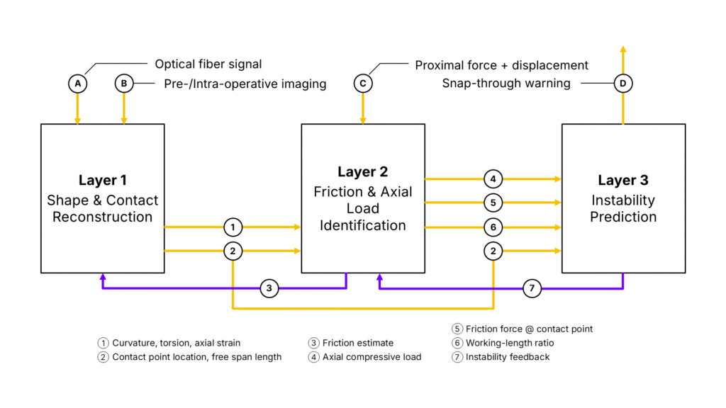
Layer 1 – Shape & Contact Sensing: This layer addresses Challenges 2 and 3. This layer takes as input the back-scattering signal of an optic fiber embedded in a neuro device and outputs a continuous profile of curvature, torsion, and axial strain along the full device length. The continuous curvature profile along the full device length has already been demonstrated in Section 2.2. F-SPINE’s novel contribution to this layer would be the derivation of torsion and axial strain.
Torsion is recovered from the helical winding geometry of the outer cores. As the fiber twists, the helical arrangement converts the twist angle into a measurable axial strain component in each outer core. Without this measurement, integrating curvature alone along the arc length would only capture the magnitude of each bend but lose track of its direction in 3D space, causing the reconstructed shape to drift from the true device path in tortuous, out-of-plane anatomy. Including torsion allows the full 3D orientation of the device to be reconstructed continuously at every point along its length.
Axial strain is measured by the central core. Because the central core sits on the neutral bending axis, it experiences no strain from bending or torsion. Any strain it registers therefore arises from compression or elongation of the device along its own length, providing a locally-grounded measurement of compressive load at every arc-length position.
This layer also outputs the locations of vessel-wall contact points and the free span lengths between them. To do so, this layer requires knowledge of the vessel geometry, specifically where the reconstructed device shape meets the vessel wall. In other words, pre-operative and/or intra-operative imaging is needed to register the fiber-derived shape against vessel anatomy. Free span lengths are then derived from the positions of consecutive contact points along the registered shape.
Layer 2 – Force & Friction Estimation: This layer addresses Challenges 1, 4, and 5. It receives as inputs the curvature, torsion, and axial strain profiles from Layer 1, the proximal force and displacement as external boundary conditions, and feedback from Layer 3 when instability is rising. It then outputs the continuous axial compressive load along the full device length, the friction force at each contact point, and the working-length ratio.
The estimation proceeds in the following steps. First, the shape profile from Layer 1 is used to set up the Cosserat rod equilibrium equations along the device. These equations relate the internal forces at every point along the device to the shape it assumes. Secondly, the known proximal force measured provides the starting point from which the filter begins computing the force distribution forward along the device. Thirdly, the axial strain from the central fiber core provides a direct measurement of compressive load at every point along the device. The filter (Layer 2) uses this measurement to correct its compressive load estimate continuously along the length, rather than relying solely on computing forward from the proximal end. This prevents estimation error from building up toward the distal tip. Fourthly, wherever the device contacts the vessel wall, the shape profile shows a sharp change in curvature at that location. The friction force at that contact point is estimated from the difference in computed force on either side of that curvature change. Fifthly, the working-length ratio is computed by comparing how far the device has advanced at the proximal end against how far the distal tip has actually moved, as tracked by Layer 1. A ratio less than 1 indicates that the proximal push is being converted into compressive load stored in the free spans along the path, rather than being transmitted as forward displacement to the tip.
Layer 3 – Instability Prediction: This layer addresses Challenge 6. It receives as inputs the compressive load, friction, and working-length ratio from Layer 2. It also receives the contact point locations and free span lengths directly from Layer 1.
The prediction proceeds in the following steps. Firstly, for each free span between two consecutive contact points, the critical compressive load at which snap-through would occur is computed from the span length and the known bending stiffness of the device. A shorter or stiffer span can tolerate more compression before becoming unstable, while a longer or more flexible span reaches its threshold sooner. Secondly, the actual compressive load in that span, received from Layer 2, is compared against this threshold. The ratio of actual load to threshold load gives the instability index for that span: a value approaching 1 means snap-through is imminent. Thirdly, this index is computed simultaneously for all free spans along the device, identifying which span is closest to instability at any given moment. Fourthly, a particle filter tracks how each instability index evolves over time. It accounts for uncertainty in the compressive load, friction, and span length estimates. The filter outputs a snap-through probability. When this probability exceeds a set threshold, a warning is issued to the user.
As shown in Fig. 1, Layer 3 also sends a feedback signal to Layer 2. When the instability index in a particular span is rising toward its threshold, it means the compressive load estimate in that span is becoming critical. Layer 3 signals the filter in Layer 2 to narrow its range of acceptable friction values at the contact points bounding that span. With a narrower friction range, the filter produces a more precise compressive load estimate in that span. This improves the accuracy of the instability index in the region where the prediction matters most.
3.3 Miniaturization Assumption
A critical engineering constraint on the clinical translation of F-SPINE is the scale mismatch between existing shape sensing systems, described in Section 2.2, and the devices used in neurointerventional diagnostics and therapy. Currently, the smallest FORS-enabled guidewire is 0.035″ in diameter. Yet, a common guidewire size for intracranial navigation is 0.014″ in diameter, or even smaller. Thus, this report assumes that miniaturization of a FORS-enabled guidewire to this scale is feasible. Additionally, as the four-core architecture is necessary to provide the axial load estimation along the device, any miniaturization should maintain this design, or provide an alternative for estimating axial load, to preserve the functional requirement for F-SPINE Layer 1.
4. Conclusion
This report presented a proposal for a framework to predict snap-through instability in neurointerventional endovascular procedures. Elastic energy accumulation and sudden release along the device body are well-documented mechanism, but currently challenging to predict. Several existing bodies of work were reviewed, each addressing a distinct component of the problem. No single work integrates them. F-SPINE proposes a three-layer architecture that connects these building blocks. Layer 1 reconstructs the continuous shape and contact geometry of the device. Layer 2 estimates the compressive load and friction at every point along its length. Layer 3 evaluates how close each free span is to snap-through and issues a warning before the event occurs.
5. References
- A. Santillan, Y. P. Gobin, E. D. Greenberg, L. Z. Leng, H. A. Riina, P. E. Stieg, and A. Patsalides, “Intraprocedural aneurysmal rupture during coil embolization of brain aneurysms: role of balloon-assisted coiling,” American journal of neuroradiology : AJNR, vol. 33, no. 10, pp. 2017–2021, 2012.
- S. H. Cho, M. Denewer, W. Park, J. S. Ahn, B. D. Kwun, D. H. Lee, and J. C. Park, “Intraprocedural rupture of unruptured cerebral aneurysms during coil embolization: A single-center experience,” World neurosurgery, vol. 105, pp. 177–183, 2017.
- Y. K. Park, H.-J. Yi, K.-S. Choi, Y.-J. Lee, and H.-J. Chun, “Intraprocedural rupture during endovascular treatment of intracranial aneurysm: Clinical results and literature review,” World neurosurgery, vol. 114, pp. e605–e615, 2018.
- H.-K. Park, M. Horowitz, C. Jungreis, J. Genevro, C. Koebbe, E. Levy, and A. Kassam, “Periprocedural morbidity and mortality associated with endovascular treatment of intracranial aneurysms,” American Journal of Neuroradiology, vol. 26, no. 3, pp. 506–514, 2005.
- K. Aoki, Y. Murayama, Y. Tanaka, T. Ishibashi, K. Irie, M. Fuga, N. Kato, I. Kan, K. Nishimura, and G. Nagayama, “Risk factors and management of intraprocedural rupture during coil embolization of unruptured intracranial aneurysms: role of balloon guiding catheter,” Frontiers in neurology, vol. 15, pp. 1 343 137–, 2024.
- T. Osuki, H. Ikeda, M. Uezato, M. Kinosada, and M. Chin, “Aneurysm perforation due to advancement of the coil delivery wire during stent-assisted embolization,” Cureus, vol. 14, no. 8, pp. e28 063–, 2022.
- H. Rafii-Tari, C. J. Payne, C. Bicknell, K.-W. Kwok, N. J. W. Cheshire, C. Riga, and G.-Z. Yang, “Objective assessment of endovascular navigation skills with force sensing,” Annals of biomedical engineering, vol. 45, no. 5, pp. 1315–1327, 2017.
- N. Li, Y. Wang, H. Zhao, and H. Ding, “Robotic systems design in endovascular treatment,” IEEE transactions on medical robotics and bionics, vol. 6, no. 2, pp. 367–383, 2024.
- N. J. Deaton, T. A. Brumfiel, A. Sarma, and J. P. Desai, “Simultaneous shape and tip force sensing for the coast guidewire robot,” IEEE robotics and automation letters, vol. 8, no. 6, pp. 3725–3731, 2023.
- J. Back, T. Manwell, R. Karim, K. Rhode, K. Althoefer, and H. Liu, “Catheter contact force estimation from shape detection using a real-time cosserat rod model,” in 2015 IEEE RSJ International Conference on Intelligent Robots and Systems (IROS). IEEE, 2015, pp. 2037–2042.
- R. G. Duncan, M. E. Froggatt, S. T. Kreger, R. J. Seeley, D. K. Gifford, A. K. Sang, and M. S. Wolfe, “High-accuracy fiber-optic shape sensing,” in Proceedings of SPIE, vol. 6530, no. 1. Bellingham, Wash: SPIE, 2007, pp. 65 301S–65 301S–11.
- M. Megens, M. D. Leistikow, A. Dusschoten, M. B. Mark, J. J. L. Horikx, E. G. Putten, and G. W. t. Hooft, “Shape accuracy of fiber optic sensing for medical devices characterized in bench experiments,” Medical physics (Lancaster), vol. 48, no. 7, pp. 3936–3947, 2021.
- J. A. van Herwaarden, M. M. Jansen, E.-j. P. Vonken, T. Bloemert-Tuin, R. W. Bullens, G. J. de Borst, and C. E. Hazenberg, “First in human clinical feasibility study of endovascular navigation with fiber optic realshape (fors) technology,” European journal of vascular and endovascular surgery, vol. 61, no. 2, pp. 317–325, 2021.
- V. Aloi, K. T. Dang, E. J. Barth, and C. Rucker, “Estimating forces along continuum robots,” IEEE robotics and automation letters, vol. 7, no. 4, pp. 8877–8884, 2022.
- A. Tamhankar and G. Pittiglio, “Towards autonomous navigation of neuroendovascular tools for timely stroke treatment via contact-aware path planning,” 2025.
- M. Razban, J. Dargahi, and B. Boulet, “A sensor-less catheter contact force estimation approach in endovascular intervention procedures,” in 2018 IEEE/RSJ International Conference on Intelligent Robots and Systems (IROS). IEEE, 2018, pp. 2100–2106.